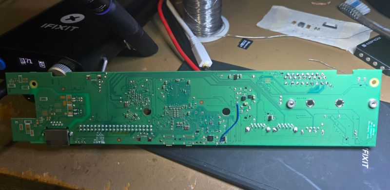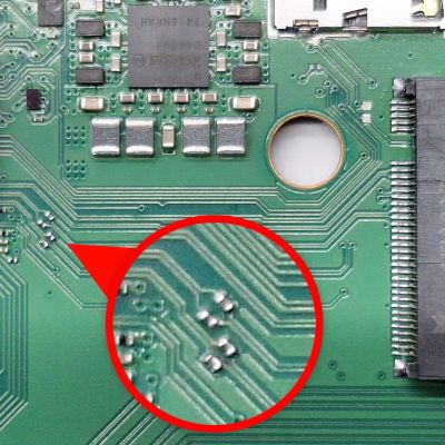
With the recent teardown of the Raspberry Pi 500, there were immediately questions raised about the unpopulated M.2 pad and related traces hiding inside. As it turns out, with the right parts and a steady hand it only takes a bit of work before an NVMe drive can be used with the RP500, as [Jeff Geerling] obtained proof of. This contrasts with [Jeff]’s own attempt involving the soldering on of an M.2 slot, which saw the NVMe drive not getting any power.

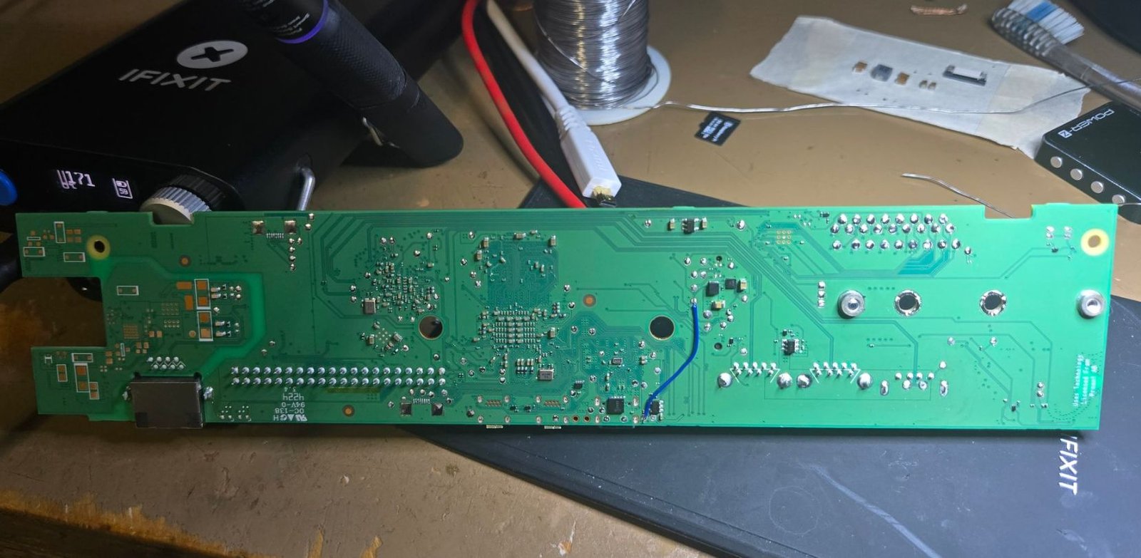
The missing ingredients turned out to be four PCIe coupling capacitors on the top of the board, as well as a source of 3.3 V. In a pinch you can make it work with a bench power supply connected to the pads on the bottom, but using the bottom pads for the intended circuitry would be much neater.
This is what [Samuel Hedrick] pulled off with the same AP3441SHE-7B as is used on the Compute Module 5 IO board. The required BOM for this section which he provides is nothing excessive either, effectively just this one IC and required external parts to make it produce 3.3V.
With the added cost to the BOM being quite minimal, this raises many questions about why this feature (and the PoE+ feature) were left unpopulated on the PCB.
Featured image: The added 3.3v rail on the Raspberry Pi 500 PCB. (Credit: Samuel Hedrick)
This articles is written by : Nermeen Nabil Khear Abdelmalak
All rights reserved to : USAGOLDMIES . www.usagoldmines.com
You can Enjoy surfing our website categories and read more content in many fields you may like .
Why USAGoldMines ?
USAGoldMines is a comprehensive website offering the latest in financial, crypto, and technical news. With specialized sections for each category, it provides readers with up-to-date market insights, investment trends, and technological advancements, making it a valuable resource for investors and enthusiasts in the fast-paced financial world.
