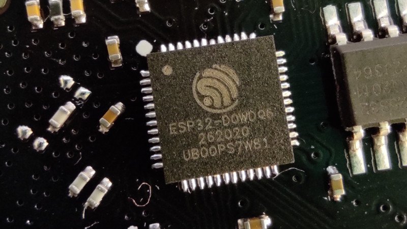
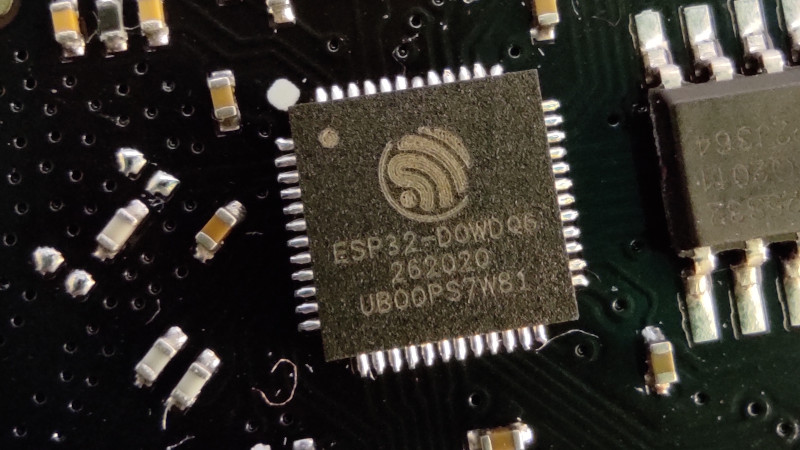
Perhaps the most exciting news of the past few weeks in the world of hardware hacking has been the unlocking of hidden SDR functionality in the Wi-Fi radios found on Espressif ESP32 microcontrollers. They can be used as both transmit and receive SDRs, and given that it’s early days for this hack we expect that great things are yet to come.
There’s one snag though, despite speculation that they might be dragged down to much lower frequencies, as far as we know they’re only proven to work around the Wi-Fi frequencies. Though the reality may be wider we’ll take that for a 2.4 GHz part as a 100 MHz slice from 2.4 GHz to 2.5 GHz. Plenty of possibilities there, and they might even work down to 1.8 GHz, but there would be so much more to do if it could work elsewhere in the spectrum. So it’s time to look at the converter, a tried and tested old way to make a radio work on a different frequency.
A Lesson From Analogue Receivers
![TV tuner front end block diagram. Derived from Chetvorno (Own work) [CC0], via Wikimedia Commons](https://hackaday.com/wp-content/uploads/2016/07/rf-front-end.jpg)
I hope most of you will be familiar with what happens when you mix two frequencies; the resulting spectrum contains both their sum, and their difference. This was the mechanism behind the tuning dial on your analogue radio or TV, the dial moved an oscillator, and a sensitive circuit tuned to a so-called intermediate frequency would filter out the difference frequency between the oscillator and the station you wanted. A few years ago we had a deep dive into the UHF hackers playground of an analogue TV tuner, where we examined this in depth.
A converter uses exactly this principle. The antenna frequency range is mixed with the output of a fixed oscillator whose frequency is chosen so that their difference represents the frequency band of your radio. THus tuning your radio tunes across the output of your mixer, which is the same as tuning across the antenna frequency range. For a numerical example, if the ESP32 receives from 2.4 GHz to 2.5 GHz, a mixer on its input with a 2 GHz local oscillator would allow the ESP32’s receiver to pick up the 400 MHz to 500 MHz band. In practice the circuit requires filters for both input and output to keep out-of-band stuff from going where it shouldn’t, but it really is that simple. Best of all, with appropriate handling of power and amplification, it works for transmitters too, and such a device is called a transverter.
Towards An Achievable Receive Converter
To make a practical converter then, we need an input filter, a mixer, an output filter, and a local oscillator. The filters are often off-the-shelf parts and needn’t be too expensive, the mixer can be as simple as a fast Schottlky diode, and the local oscillator could even in this case be another ESP32, they’re that cheap. You can add amplifiers if you want and what I am about to describe is a somewhat janky receive converter, but it can be made to work.
The Filter
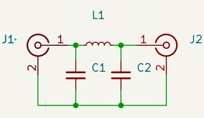
In most cases such a converter will be intended to receive signals lower than the ESSP32’s range, so let’s assume you’re looking somewhere from HF through to VHF. The input filter has to reject anything above your maximum input frequency and stop any stray local oscillator leakage to the antenna, which most of you will identify as a low-pass filter. These can be bought off the shelf for a price, but are easy enough to make for yourself.
The most common low pass filter is often referred to as a Pi network because its circuit superficially resembles a Greek letter Pi, and takes the form of an inductor in the signal path with a capacitor to ground either side of it. If you know your maths you can calculate the values for yourself, but if you don’t there are many online Pi network calculators to help you. Constructing a Pi network at these frequencies is straightforward enough.
For the output filter, you need something that rejects the local oscillator frequency as much as possible, and passes the ESP32 receive range. Here you’re in luck, because the Wi-Fi hardware industry needs exactly those filters, so they can be had from Mouser or Digi-Key for cheap. I’m not going to specify a particular part, but I’d like to point you at the TDK Wi-Fi filter range and invite you to pick one with the bandwidth you need.
The Local Oscillator
Your local oscillator for an ESP32 working at much lower frequencies is likely to be around or above 2 GHz. Back in the day you would have used a crystal oscillator and multiplier circuits, if you like you can buy an expensive PLL oscillator module, but your simplest and probably cheapest method is to use another ESP32, now that it can be used as an SDR transmitter. Program it to output a single carrier on your desired frequency, dial down the output level, and there you have it, a 2 GHz local oscillator for a dollar or two.
The Mixer
Yet again you can buy an off the shelf mixer as a module, though one for a 2.4 GHz output will be expensive. Happily there’s a simple circuit which can do the job, and it uses a diode as a non-linear element fed with both antenna and local oscillator signals. At these frequencies you are looking for a very fast small-signal Schottky diode with as low a capacitance as you can find, and happily such parts are available from multiple manufacturers at cent rather than dollar prices. The basic circuit is shown below, and as you can see it’s quite simple.
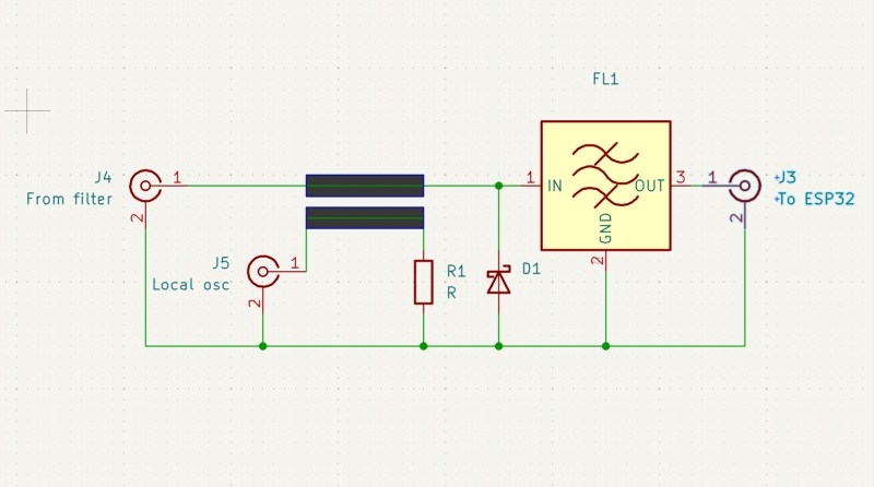
In the circuit above the diode is your Schottky device, the input low pass filter isn’t shown, and the output filter is an off-the-shelf Wi-Fi bandpass filter. The two thick lines represent a stripline coupler, and they are simply two parallel PCB traces side by side over a groundplane. Their size should ideally be calculated to present the right impedance, often 50 ohms which is also the value of R1, but in practice the jankiest solutions can work here. With an ESP32 as a local oscillator I would hazard a guess that laying the trace on the PCB under the module’s antenna with the power turned down would be enough. I may earn the scorn of some of my peers, but I have a long history of RF bodging and I think it might just work.
Making It Transmit
The same technique as above works for shifting the ESP32’s transmit output down to the desired frequency, but there’s a catch. Even the modest output from an ESP32 can be enough to damage or overload parts designed for receivers, so you have two choices. Pick transmit-appropriate parts, or dial back the power to a low level, and amplify it at the lower frequency.
By Now, You Should Be Able To Bodge A Converter
The information above isn’t a ready-to-go design for a receive converter to get your ESP32 listening to lower frequencies, but it should give you all the signposts you need to get there. People have built converters for the RTL-SDR for ages now, so you could pilfer ideas there too. If you build a downconverter, for transmit or receive or both, let us know!
At a superconference about a decade ago there was a talk about RF construction techniques which will save you a lot of pain, and with luck such a simple circuit should be within your grasp. Good luck.
This articles is written by : Nermeen Nabil Khear Abdelmalak
All rights reserved to : USAGOLDMIES . www.usagoldmines.com
You can Enjoy surfing our website categories and read more content in many fields you may like .
Why USAGoldMines ?
USAGoldMines is a comprehensive website offering the latest in financial, crypto, and technical news. With specialized sections for each category, it provides readers with up-to-date market insights, investment trends, and technological advancements, making it a valuable resource for investors and enthusiasts in the fast-paced financial world.